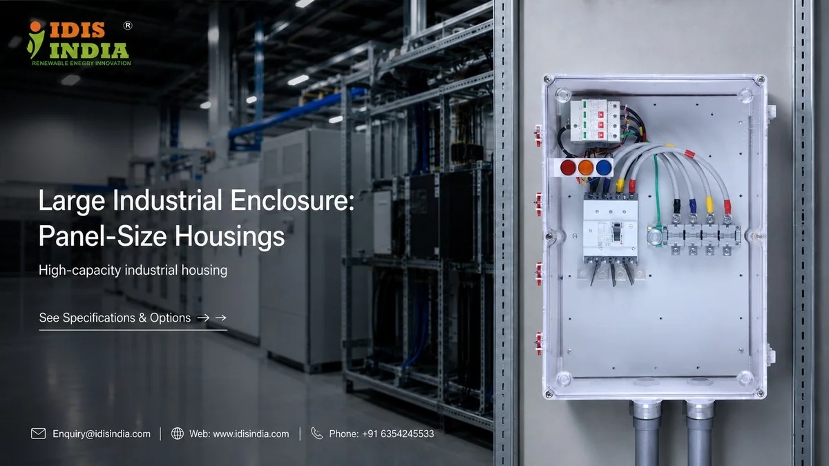
If you are designing a control panel or an enclosure for a VFD system then the size of the enclosure is very important. I-closure’s large industrial enclosures will give you the room and structural integrity that you require when creating complex electrical assemblies.
I-closure’s enclosures range from approximately 400mm x 300mm to 600mm x 500mm and can accommodate multi-level control systems and oversized power components. When considering your engineered solution, engineers and builders need more than just space, they need engineered solutions; therefore, I-closure’s large industrial enclosures provide the answer.
The large industrial enclosures from I-closure have an IP67 or IP68 rating allowing for a protected area in which to install your expensive equipment, as well as providing enough floor area to complete your professional installation.
Panel Capacity Load Calculations
What is the weight limit for your enclosure? The fundamental principle of utilizing your enclosure for support is the total load applied to the various mounting points, hardware components, and structure of the unit. Heavy-duty enclosures from I-closure can accommodate a variety of distributed load weights. For example, the distributed load capacity for I-closure’s heavy-duty enclosures ranges from 50-80 kg per model and per mounting configuration, but the biggest challenge is the amount of concentrated point loading created by large components, such as transformers and VFDs, within the individual enclosure. As an example of point loading, a 15kW VFD typically weighs 25-30 kg and creates a point load that exceeds the manufacturer’s recommended capacity in a standard distribution load capacity; therefore, you’ll want to ensure the mounting rails of your enclosure will distribute these point loads evenly to the back of the enclosure. IDIS India builds all large enclosures with reinforced mounting zones; therefore, if you are installing heavy components to your enclosure, the calculated distributed load will account for the combined weight of all your heavy components, and the point load will be based upon the weight of the individual heavy components. Additionally, while determining the maximum distributed load for an enclosure, you should also consider the maximum dynamic load; dynamic loads can be caused by vibration and/or thermal expansion. Additionally, the safety factor used for heavy-duty industrial applications is between 2:1 to 3:1. Finally, your large enclosure’s mounting rail spacing conforms to standard DIN rail mounting spacings with additional structural support, thereby ensuring that the mounting rails will provide maximum support to your heavy-duty components throughout the duration of their continuous operation and thermal cycling.
Structural Reinforcement Requirements
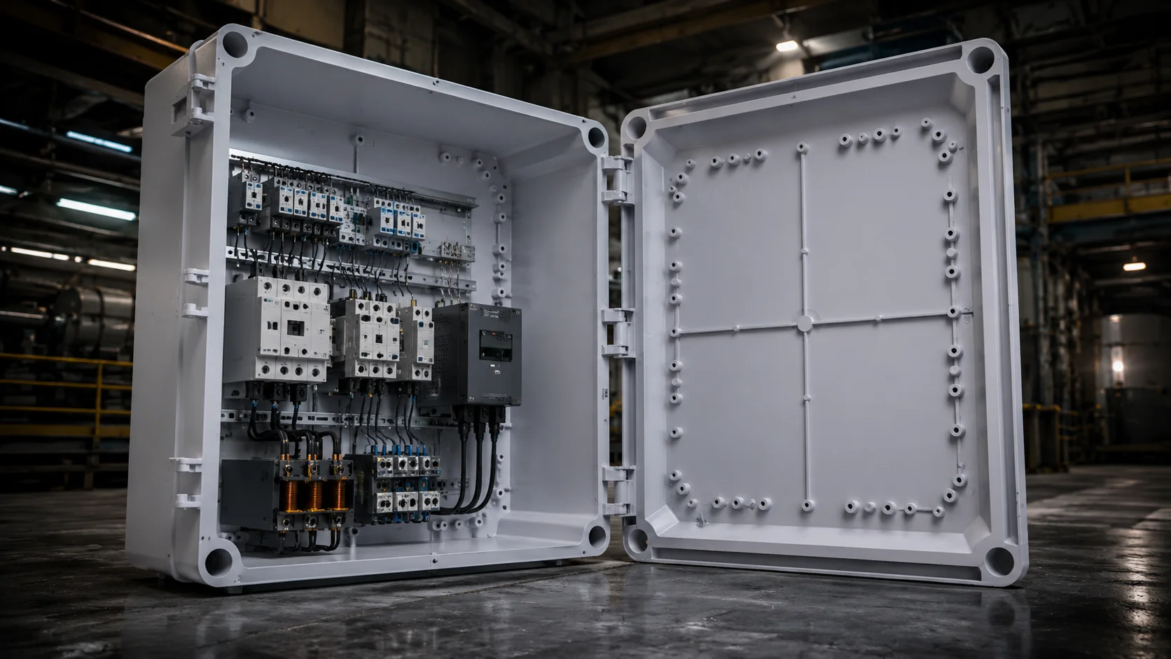
There are particular structural challenges associated with large enclosures. As the size of the enclosure increases, the ability to flex and distort increases as well. For large enclosures, the I-closure utilizes a strategic design of reinforcement to support the weight of the enclosure while maintaining the necessary rigidity without unnecessary weight.
To support the strength of the large enclosure, the corner joints use also reinforced to support the both load developed by the internal components and the gravitational force developed by the use of external mounting hardware. This is particularly important when you are using wall mounting hardware because the distributed weight of the entire assembly must be felt by all mounting points without creating a stress concentration against the mounting surface.
Reinforcement to the back panel of large enclosures varies, depending on the size of the enclosure, but typically contains Cross-bracing elements that prevent the panel from bowing under load Reinforced mounting zones at standard DIN rail locations Rigid structural ribs, as a mechanism for isolating stress, throughout the back panel Corner gussets to maintain the dimension stability of the enclosure.
What about sagging doors? Large doors place tremendous cantilever loads on the hinge system. I-DIS India incorporates multi-point configurations in its hinge systems and provides edge reinforcement in the doors in order to limit the long-term deformation of the doors.
Oversized Component Accommodation
The traditional enclosure design of industrial components is growing larger. With large motor starters, soft starters, and VFDs being case in sizes that were never considered before, it is important to take sizing into account when selecting large enclosures for industrial applications. I-closure manufacturers anticipate the new needs of large industrial enclosures by providing internal depths typically between two hundred and three hundred millimeters, allowing large industrial components enough room for both deep components and wiring. The need to consider depth also becomes a priority when installing components that require rear ventilation or cable access. Calculating the amount of space needed for each component based on the factors stated above must also include: areas with heat generating components that require airflow through them; clearances required for the service and maintenance of that particular component; clearances needed to accommodate the bending radius of wires; and any future expansion that will be required to accommodate additional components. So what happens when components exceed the typical mounting pattern? Many large transformers, custom fabricated assemblies, and other specialized pieces of equipment may require a non-standard mounting method. Many of the large enclosed I-closure enclosures utilize reinforced back panels that will accommodate either standard or custom mounting hardware.
Thermal Clearance Planning
Components that generate heat need space to breathe. Thermal management in large enclosed spaces is more than a question of providing airflow for cooling; it is also about developing a strategy for the arrangement of the various components. The ideal position of all high-heat generating components is to promote improved airflow and allow for servicing.
Multi-Level Mounting Systems
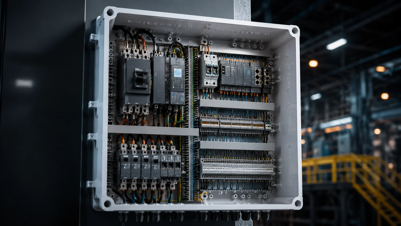
Many industries use complex control panels. Complex control panels normally have several levels of components. Industrial enclosures made by IDIS India allow use of both horizontal and vertical mounting arrangements to best use available space. The multi-level approach to mounting typically includes: Primary mounting level for power components; Secondary level for control devices and interfaces; Terminal strip levels for organizing wires; Dedicated channels for cable management.
Multiple depths for mounting components on a DIN rail can be created in the large enclosure so that different component types are mounted and remain accessible for installation and servicing. However, mounting of components within large industrial enclosures is not merely to provide physical support, but also to provide organized routing of power, control, and communication wiring within the enclosure. The I-closure design includes built-in wire management to maintain an orderly installation of wiring and to provide for ease of servicing.
Component Zoning Strategy
Heat and electrical noise are generated by power components. Control components rely on being isolated from both sources of interference. Multi-level mounting systems improve electromagnetic compatibility (EMC) and thermal management through physical separation.
Large Door Hinge Engineering
Industrial enclosures with large doors are exposed to some of the most significant mechanical problems achievable through design. The door will also be heavier due to its size resulting in larger than average cantilever loads causing the hinge assembly to be unable to support the weight of the door. Consequently, poor design of the hinge will result in sagging of the door and ultimately failure of the sealed surface, leading to security issues. The engineers at IDIS India utilize multi-point hinge systems to provide adequate weight distribution for the door on large enclosures utilizing flexibility of the hinge spacings to optimize accessibility and have the necessary number of hinges to provide for the structural integrity required for the door without causing interference with items inside the enclosure. Some important considerations for the engineer to consider when designing the door of a large enclosure are as follows: Hinge load capacity must be matched to the weight and overall size of the door; The frame of the door must be reinforced; The hinge assembly must be adjustable in the field; The compression of seals must be maintained consistently around the door; The locking mechanism must be proportional to the size of the door; Large doors have high internal pressure during thermal cycling, therefore, must have a robust latching mechanism that maintains seal compression. The use of multi-point latching systems firmly maintains the compression of the seal on large enclosures.
Door Weight Distribution
A considerate amount of balancing will occur between each hinge in a heavy door’s installation. The hinge on the top side of a heavy door will have the most weight or load above it, which is reflected in the hinge since the load is distributed over the entire door from top to bottom. Picking the proper size and spacing of your hinges will help ensure that, over time, the hinges do not deform and retain their sealing efficiency.
Thermal Management Scaling
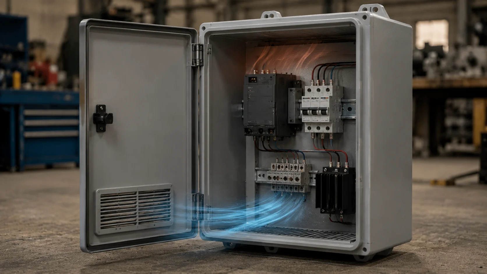
As large enclosures create more heat, they also require increased cooling relative to size. However, thermal management requires more than simply adding larger fans; you must also understand how heat is distributed in large enclosures and how air flows through them at higher volumes of space. Natural convection in large enclosures operates differently than when using smaller enclosures. The stratification of hot air in large enclosures creates pronounced heating differences across distances, and the resulting temperature differences can have an effect on the performance of components. When designing forced airflow systems, it is important to properly place the components within the forced air system to provide sufficient cooling while avoiding excessive pressure differentials. Thermal management scaling factors include: Mapping out the amount of heat produced by each component Properly optimizing the route of the airflow through the enclosure Determining the appropriate size of the forced airflow device Implementing temperature monitoring strategies I-closure ‘ large industrial enclosure ventilation systems have “pre-engineered” mounting provisions. Mounting points for fans, filters, vents, etc. were created to preserve the enclosure I.P.65 or I.P.67 rating while simultaneously providing effective thermal management capability. What about passive cooling? Larger enclosures are better suited for dissipating heat due to the higher surface area to volume ratio of their exterior surfaces, however, their interiors are usually very dense with many components, therefore they will generally require some form of active cooling.
Heavy Assembly Transportation Methods
Large, industrial enclosures become cumbersome and heavy to move, once they are fully populated with their components. From the design of the enclosure itself to the installation process, transportation planning should always be a consideration. At IDIS India, we incorporate the requirements for transportation into the design of the structural component of large enclosures. Lifting points, handling features and modular assembly options will assist with the logistical challenges of large/heavy installations. When considering transportation, the following typically apply: Enclosure weight distribution to ensure balanced lifting – Handling features to facilitate manual location of enclosure – Accessibility of mounting hardware – Protection during transport and storage of enclosure – While many large control panels carry populated weights of 100kg plus, therefore requiring professional installation procedures and possibly specific lifting equipment, the mounting system of an enclosure must be designed to withstand the static and dynamic loading during the installation process.
Installation Planning
When preparing to install heavy assemblies it is essential to create an installation plan that considers the access route to the installation site, lifting devices used to lift the assemblies off the ground and their final location. Mounting provisions are included on all I-closure industrial enclosures that will accommodate the different types of mounting conditions, including both wall and floor mounted installations; therefore, the structural interface used to support the complete assembly must provide adequate support to safely carry all loads of the system. Maintenance access is equally important, since inefficient serviceability of the assembly can result in long-term operational issues. If you are interested in discussing your needs for an industrial enclosure please contact IDIS India. Our engineering staff can assist you in determining the appropriate housing solution based upon the size of the panel(s) you are using; thereby providing you with a product that will maintain structural integrity and long-term durability/operational reliability for your industrial installations.