
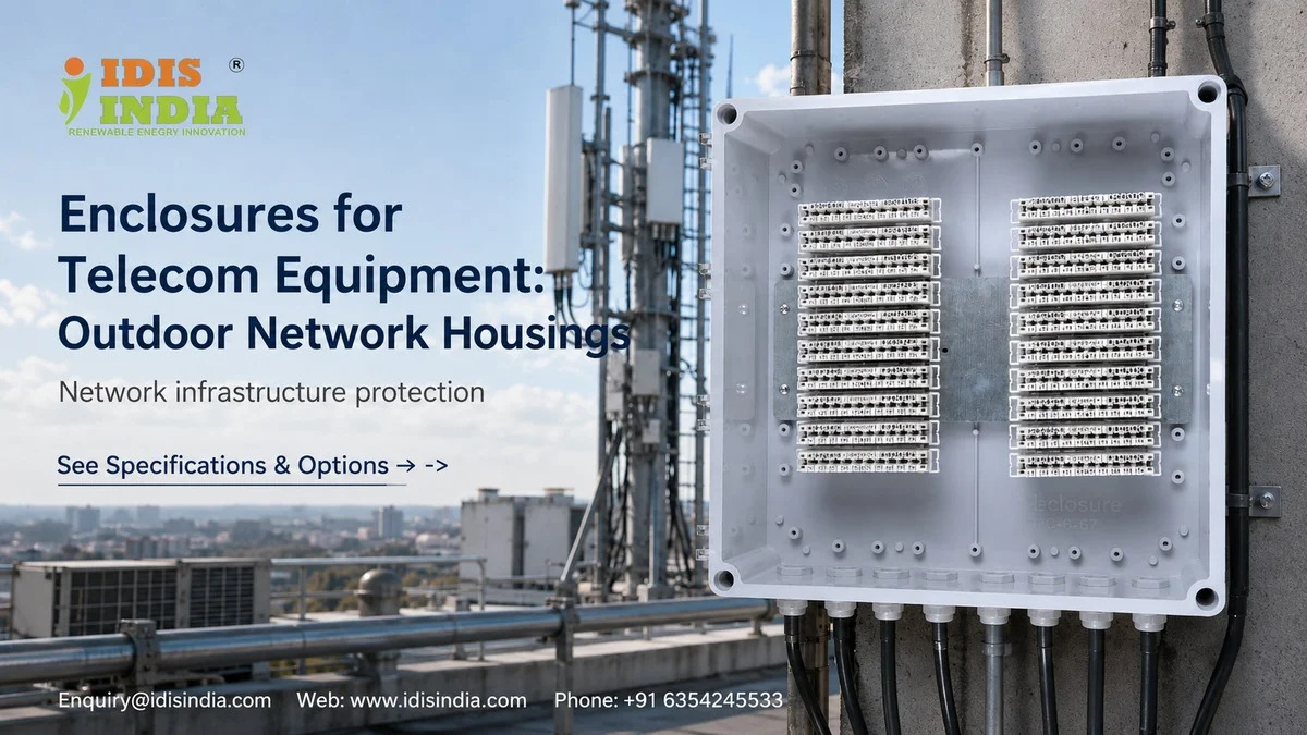
Everyday outdoor weather has historically posed a challenge to telecommunications networks, subjected to extreme environmental elements such as rain, dust, extreme temperatures, and direct sunlight that can adversely affect sensitive telecommunications electronic equipment. With proper outdoor housing solution options, telecommunications companies can maintain operational reliability while minimizing service interruptions. At I-closure, we have comprehensive knowledge of telecommunications engineers’ needs and the ability to manufacture market-leading enclosures that provide protection and reliability for critical infrastructure and high-quality signals. With more than 1200 active customers, I-closure has experienced all aspects of telecommunications’ ever-changing technological, business, and operational landscape.
Tower Mount Vibration Analysis
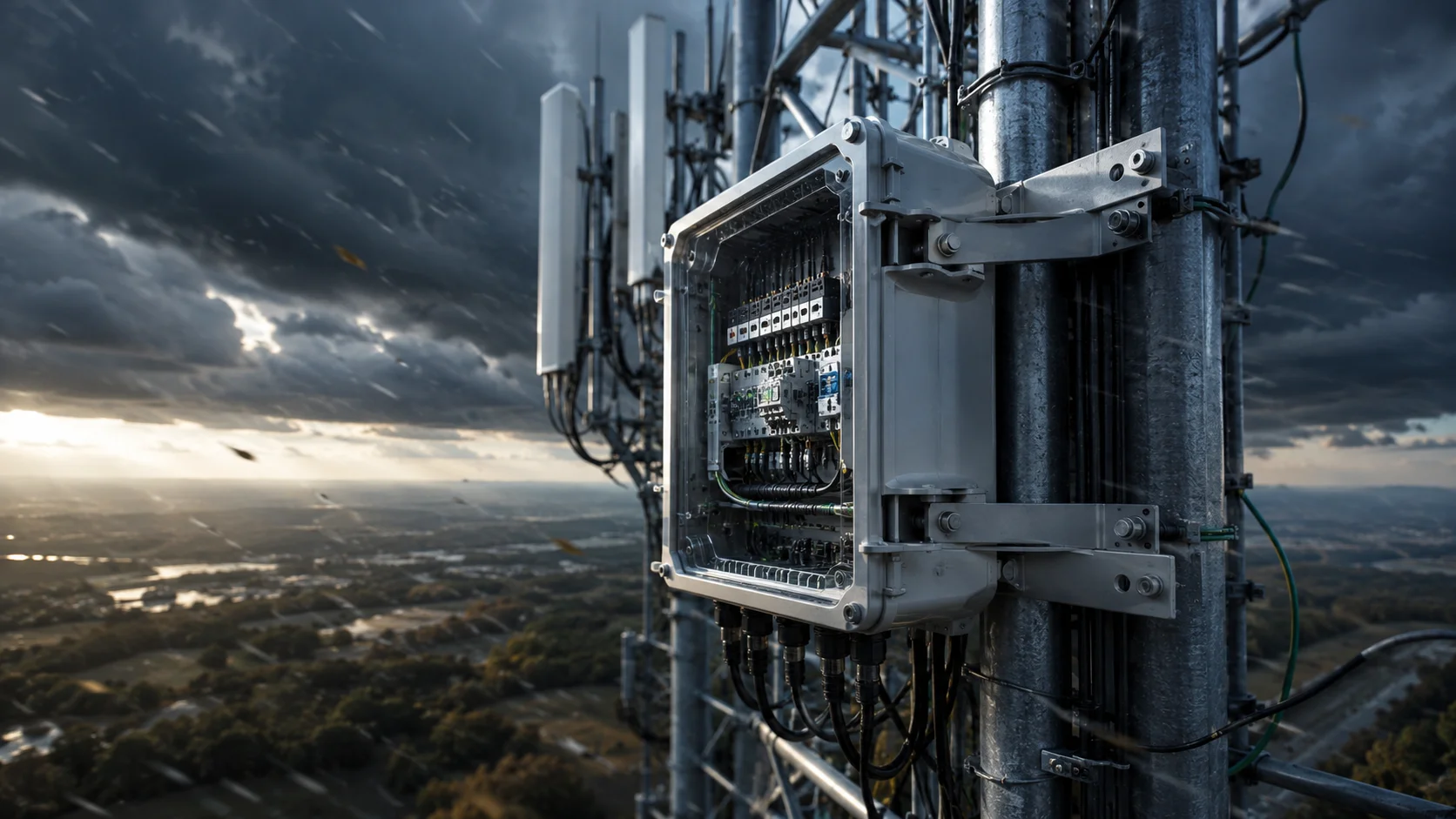
Mechanical stress caused by wind loads creates constant vibrations on cell tower equipment and can cause damage to sensitive electrical components over time. What’s the best way to solve these types of problems? The proper enclosure design that takes dynamic forces into consideration. In the case of our polycarbonate enclosures used for tower mounting, most enclosures are designed with reinforced mounting brackets that effectively distribute all stress across the entire wall of the enclosure instead of concentrating it solely at the bolt points. The end result is fewer fatigue cracks and longer life of the enclosure components within the tower-mounted enclosures. While the environmental conditions at the top of the tower do pose unique issues, another source of mechanical stress is evident during thermal cycling. Typically, we experience temperatures ranging from as low as -40 degrees C to as high as 70 degrees C on a constant basis. Our I-closure housings utilize flexible mounting systems that are specifically designed to accommodate thermal expansion and contraction without losing the base enclosure’s IP65 rating. In addition to the stresses created by environmental conditions caused by thermal expansion and contraction, vibration also has an effect on the internal components housed within enclosures. For example, if an internal component is mounted to a DIN rail using only mechanical fasteners, there is a high probability that the internal component will move out of alignment due to continuous vibration. The benefit of using our enclosures is that each enclosure is equipped with integrated mounting points for the DIN rail, which ensure proper alignment is maintained even when subjected to continuous vibrations.
5G Small Cell Integration
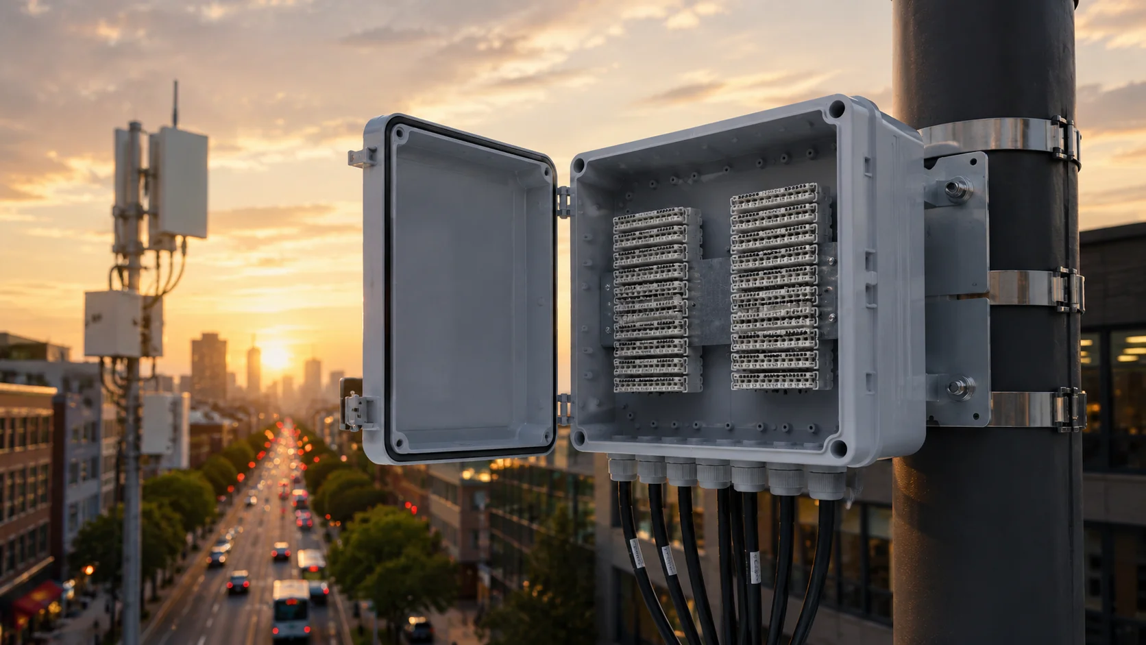
The way that 5G networks will be implemented will mean that their enclosures must therefore take a very different approach to Macro cell site enclosure At the same time small cells are typically smaller, lighter and located closer to ground level; they still must have effective enclosure protection. A critical issue with 5G is the size of the application. Our compact enclosures starting at approximately 300 x 250 x 150 mm in dimension can accommodate the required size of BTS Controller equipment while maintaining lower visual impact. Additionally, urban installation benefits from the small size of these enclosures. Heat dissipation will be highly important for 5G Small cell applications as their processing power is significantly increased, generating large amounts of heat in small enclosures. The IDIS India Enclosure can be fitted with ventilation options for cooling and/or thermal management depending on your preferences. Lastly, flexibility in mounting is also extremely important for small cells; therefore, in addition to wall mounting, our modular bracket system design will support pole or strand mounting configurations for versatility in installation without requiring custom tooling for every different application or location.
Fiber Splice Compartment Design
The features required by a specialized enclosure for a fiber optic network are vastly different than that of any conventional enclosure. Each element of cable management, splice management, and bend radius protection must all be considered when designing an enclosure for use with a fiber optic cable system. Generally, these enclosures are normally built using standard material and equipment enclosures but fall below the quality standards because of multiple points of entry and exit of optical fiber cables. Handling the entry of multiple optical fiber cables into an enclosure is typically handled by M25 and M32 types of cable entry glands. Maintaining the proper seal at the entry point requires a high level of attention to detail. The enclosure’s entry point(s) must provide a minimum of IP65 rating for moisture and dust protection while allowing movement/flexibility of the cable conduits. The internal organization of the enclosure must be done in a manner that prevents the disruption of service during repair of the enclosure or the cables inside of it. Splice mounting systems within the enclosure should provide stable support points for mounting the standard splice hardware of the different manufacturers being used in conjunction with the enclosure. In order to optimize the amount of space required within the enclosure and utilize the enclosure to its maximum potential, most terminations are approximately 4000mm x 300mm x 200mm. Some larger installations may require a housing that is approximately 600mm x 400mm x 300mm based on the amount of fiber and the number of splices required.
RF Signal Interference Prevention
The performance of telecom equipment can be affected greatly by electromagnetic interference, with metal shielding often creating undesired shielding effects as well. The key is to select materials carefully as well as optimize your design so that it meets the needs of your application while simultaneously achieving good performance. Polycarbonate enclosures provide RF transparency as needed, allowing antenna signals to pass through them with little or no loss. This is especially critical for applications where the enclosure is located between the antenna and equipment (i.e., an external antenna feeding into the enclosure’s interior). When the receiver equipment is sensitive enough, an EMI (electromagnetic interference) shield should be implemented. If necessary, optional conductive coatings or gaskets will offer shield properties in addition to being able to act as thermal management solutions. However, the need for proper grounding systems to achieve EMI performance cannot be overstated; therefore, our enclosures come equipped with grounding points in order to connect to the grounding systems located at the towers. As a result, damage from lightning strikes and static buildup can be avoided.
Network Equipment Cooling Optimization
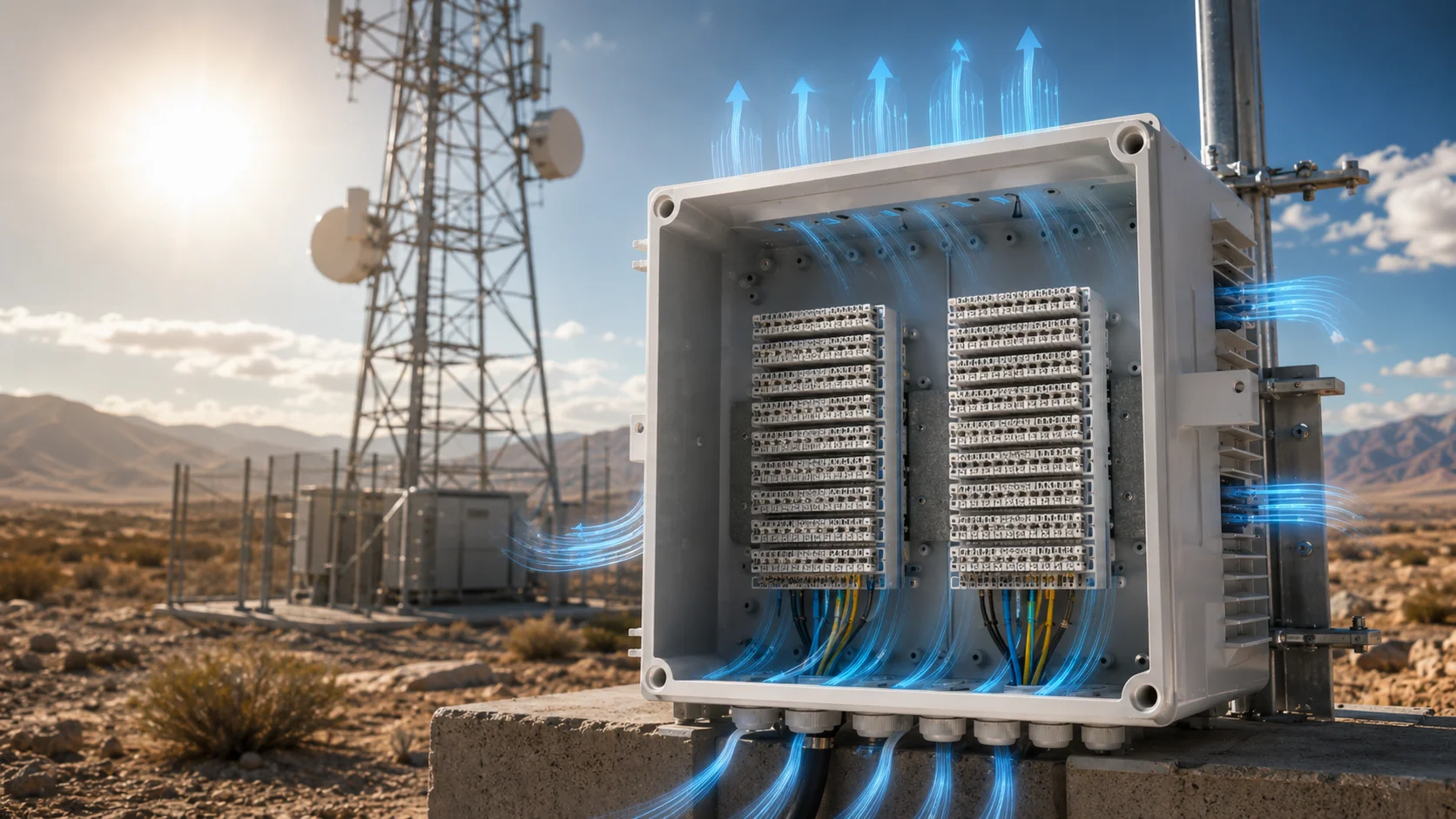
Thermal management of telecom equipment allows for operational sustainment of equipment. External air temperature varies greatly, and internal temperature is influenced by heat produced from the operation of the equipment. When the cooling of the equipment is not adequate, the equipment will operate for a lesser length of time and require service interruptions. The selection of colors also greatly impacts the thermal performance of equipment; for example, light colored surfaces have a higher reflection of solar radiation than do dark colored surfaces. This reflective property allows the internal temperature of an enclosure to be lower by several degrees at peak sun exposure. Additionally, the design and use of ventilation are critical decisions associated with thermal management. Natural convection is well suited for low vapor pressure, low wattage, low level heat producing equipment, while forced air-cooling would be appropriate for high wattage heat producing equipment. There are enclosures where I-closure will permit ventilation openings without compromising the IP65 rating, such as an outdoor enclosure with multiple ventilation opening arrangements. Finally, the thermal conductivity of a material determines how well a material meets a variety of thermal performance requirements. For example, a polycarbonate material has very good thermal stability in the full temperature range of materials, and polycarbonate will not become brittle under low temperature conditions.
Antenna Feedthrough Weatherproofing
The antenna connectors represent the greatest challenge in terms of weatherproofing; all three types of antenna connections require reliable sealing (coaxial cable, waveguide, and fiber), as the failure of a single seal could cause the failure of some very costly equipment. The cable entry system needs to accommodate various connectors (for example, N-type, 7/16 DIN, fiber optic, etc.) that have different sealing requirements. Many standard cable glands do not provide adequate protection for the individual connectors used in a communication system. Weatherproof connector panels have been developed to integrate multiple connector types in a single, sealed unit, thus providing ease of installation and reliable environmental protection. However, all types of sealing systems will be affected by thermal cycling, and the expansion/contraction of the materials may lead to the failure of the gasket seal over time. Routine maintenance schedules should include routine inspection and replacement of seals when necessary.
Remote Site Security Features
Many telecom sites exist in remote areas with little or no security available, and equipment theft and vandalism can severely disrupt service delivery. Therefore, added emphasis should be placed on physical security for outdoor installation of telecom equipment. Weather-resistant, tamper-resistant locking systems have become necessary for outdoor telecom equipment; however, standard locking solutions will freeze during winter or corrode under marine conditions. Specialized hardware can keep the locking functionality intact regardless of weather; for example, anti-theft mounting prevents the complete removal of the enclosure. Through-bolting with concealed fasteners makes it almost impossible to remove these systems by someone who does not possess proper authorization, therefore protecting both the enclosure and internal equipment. Rapid-release, or quick-release mechanisms, help authorized technicians by providing them with rapid access to equipment for maintenance and/or troubleshooting of equipment issue. However, careful attention to the security requirements needs to be made when designing a quick-release mechanism. Visual deterrents are also a part of the design. The installation of equipment in a professional manner makes it appear to be valuable equipment located inside. In some cases, a simple, utility-type appearance may serve to decrease the motivation for the perpetration of theft, while still accomplishing the desired functionality.
Choosing the Right Telecom Enclosure
Every telecom application has specific needs. Towers must be vibration resistant. Small cells need to be small in size and look nice. Fiber nodes need to manage cables well. The key is matching the capabilities of the enclosure with the actual install requirements. Material selection impacts performance over the long term; most applications will see the advantages of using polycarbonate because it provides UV stability and impact resistance. Most installations will be less demanding of the enclosure so using PC/ABS combinations can provide the cost advantages.
Size requirements will depend on the specifications of the equipment as well as any future installation expansions. Starting with adequate space can help prevent upgrading your enclosure due to a lack of space in the future. However, using an enclosure that is oversized can cause the box to be more expensive and create unnecessary complexity in installing it.
IDIS India has given telecom equipment enclosures in many telecom installations. Our ISO9001 certification and CE compliance ensures consistent quality in both manufacturing and performance. Our NABL accreditation allows us to provide testing for the performance claims we make.
If you have questions about how to select the right enclosure for your telecom project, please contact our technical team for guidance on application-specific requirements. We are able to make recommendations based on your complete enclosure requirements as well as the conditions of your enclosure installation.
Need Help Choosing the Right Enclosure? Get in Touch!