
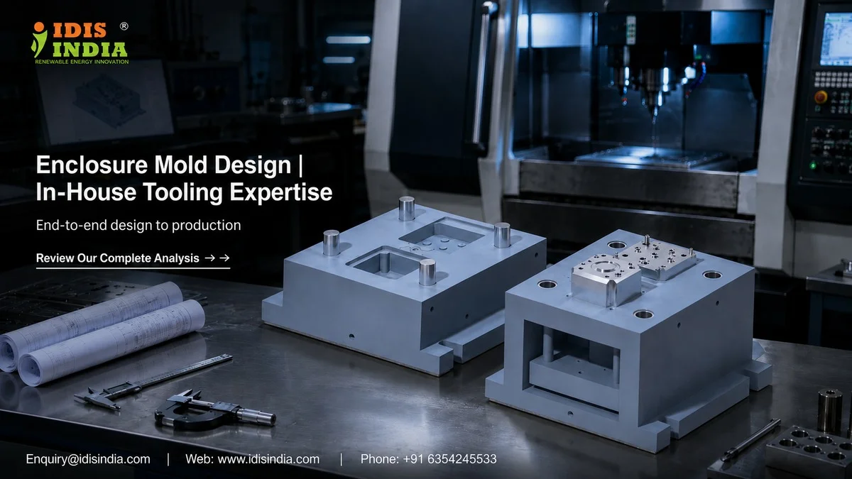
The quality of enclosure moulding is critical to meeting the high standards of accuracy and repeatability that your project needs. At IDIS India, we are equipped with in-house tooling capabilities which allow us to create an integrated process from the initial design to the final production of enclosure moulding that will provide you with IP65 and IP67 rated enclosures, with all dimensions being accurate. What differentiates good mould engineering from expensive mistakes? The short answer is a complete understanding of the entire process and professional engineers who can optimise every aspect of the design. We have honed this methodology on hundreds of custom projects, and now we are ready to share our expertise with you!
Design Process Foundation for Custom Enclosures
To create a successful enclosure mold design, it is important to first understand your specific needs. We will start by analyzing the dimensions of the product, materials you want, and environmental protection requirements with our engineers. It’s not only creating a cavity; we’re also designing an entire solution.
The first design stage will generally involve many key considerations as follows: the manufacturability and the material flow path must accommodate any variation in wall thickness while maintaining sufficient structural integrity; the location of the parting line will affect both aesthetics and sealing performance for IP-rated applications; and we document all of these requirements during this stage.
Mold design architecture is also influenced by how the connector will be positioned in relation to the parting line (e.g., whether it will be mounted or not) and/or cable entry. Any minor mistakes in one of these areas can lead to costly revisions later.
Mold design validation is performed through multiple iterations. Our team will produce mechanical drawings for review, talk about possible manufacturing challenges, and make recommendations for design changes prior to ordering steel for mold construction. This combined effort allows us to address issues before the actual cutting of steel.
CAD/CAM Capabilities and Software Integration
High-tech CAD CAM systems dominate today’s enclosure mold designs. At I–closure, we use standard industry–wide packages to provide accurate models of all our enclosure designs and transfer data easily to machines. Careful consideration is taken when designing complex geometric shapes (e.g., multi cavity layouts, cooling channels), where virtually all the parts of the design are created as 3D representations prior to any machining activity. Once designs are modeled in 3D, we then program them into machine code using CAM programming software that generates the toolpaths needed for machining with our CNC equipment. We ensure we optimize the movement of tools to ensure accuracy and surface quality on parts being manufactured as IP65 and IP67 meets these requirements. All of our software programs are integrated, which eliminates all problems associated with entering data manually into systems. When a design change occurs, the design changes propagate automatically throughout our entire manufacturing process, therefore decreasing wait times and helping to guarantee consistency in the project. This is critical when our customers have short delivery times.
Mold Flow Simulation for Optimal Material Distribution
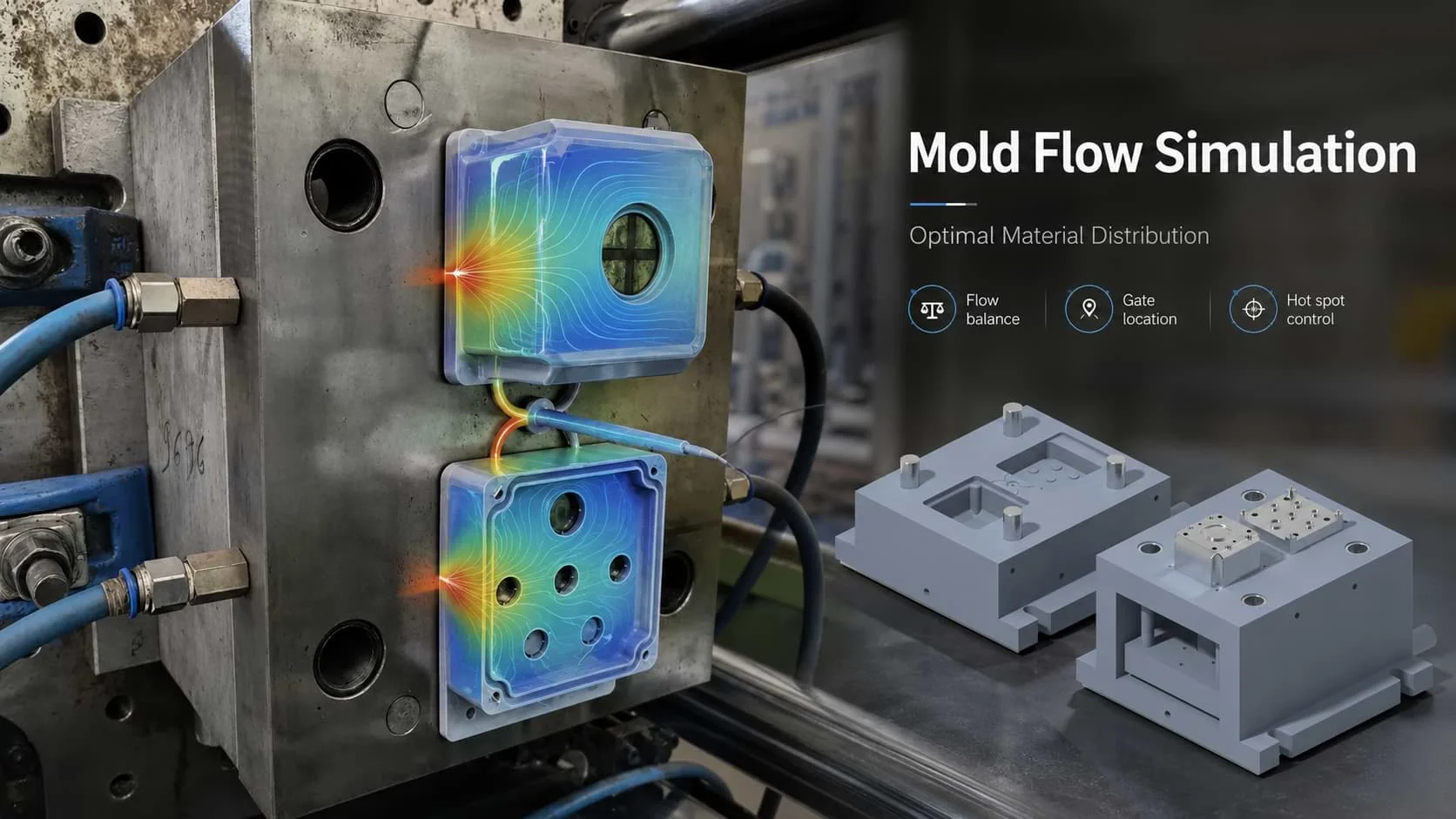
A good understanding of how molten plastic flows through a mold is vital for successful injection molding. Using our simulation software allows you to predict problems with your part and eliminate waste before the construction of the mold. Flow analysis shows how ABS, Polycarbonate, or combinations of PC/ABS will fill different enclosure geometries. Each type of material has its particular flow characteristics, therefore the simulations used account for these differences. The flow results are used as criteria for making important design decisions. The gates that will allow molten plastic to enter the mold cavity are located, sized, and venting planned based on the flow predictions to eliminate common manufacturing defects such as short shots, sink marks, and weld lines in critical or aesthetic locations. The filling of the cavity is monitored to analyze the pressure and temperature distributions applied to the molten plastic as it enters the mold cavity. Any hot spots that have the potential to degrade the material will be either eliminated by adjusting the cooling channels or changing the cycle parameters.
Strategic Cooling Channel Design
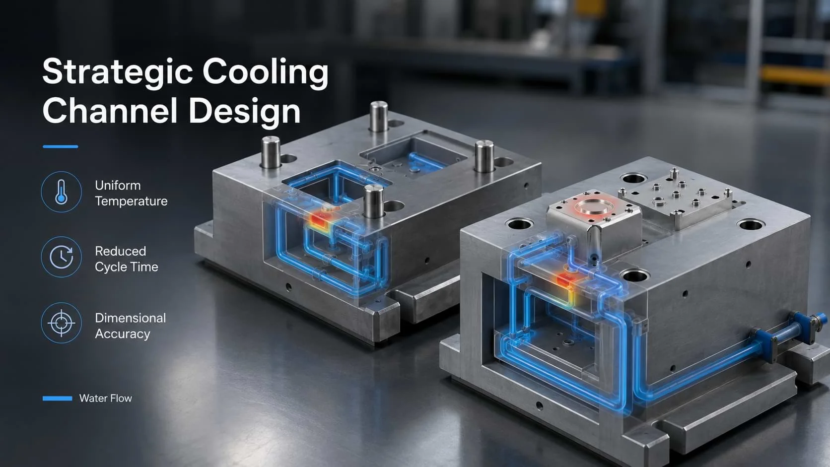
Production efficiency and part quality are directly affected by effective cooling. Our cooling channel design guarantees that the temperature in the injection mould is evenly distributed across the entire mould allowing for the smallest cycle times and maintenance of dimensional accuracy. The location of the channels is designed according to established thermal management principles. Areas where there are very thick sections or gates have been designed with the highest level of cooling to eliminate defects. Conformally cooled channels may also be included for moulds with complex geometries. Water flow calculations are performed to ensure the required heat removal capability of the cooling channel. At the time of the design of the cooling channel, specifications will be established for the channel diameter, connection method, and flow rate. Reducing warpage and improving surface finish result from the application of effective cooling to the production process. As part of the design, temperature monitoring capability will be included in the design and location of thermocouples and data acquisition connections should be established to facilitate real time process monitoring during production runs.
Gate Location Optimization for Quality Results
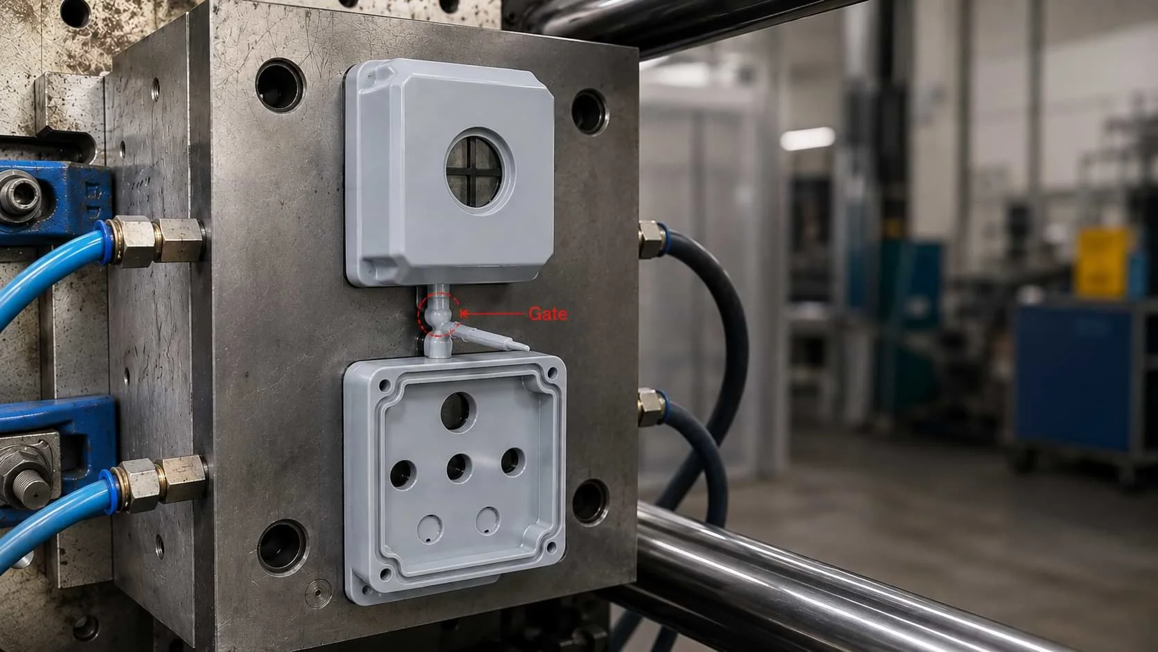
How to place your gate will impact both your part quality and production efficiency. Our engineers determine the type of gate(s) and the gate placement based on the geometry and performance requirements of your enclosure. Aesthetic considerations typically guide gate placement decisions. When considering the visible surface, the gate locations will either be in places where marking will be minimized or where marks will be easy to remove through later finishing processes. Mechanical properties will vary around a gate location due to the effects of molecular orientation; critical stress areas are analyzed to ensure that gate placement does not negatively impact structural integrity. Depending on the size of the enclosure, a variety of gating strategies could be used. Balanced filling enables reduced injection pressures while still producing a uniform wall thickness distribution in the enclosure. Balanced filling is especially important for IP-rated housings, as the sealing surfaces must remain flat.
Ejection System Engineering
Carefully designed ejection systems allow for reliable part removal. When specifying configurations for ejectors, we take into account the geometry of the part, the material properties of the component, and any production automation requirements.
Ejector pin placement is critical in ensuring that pin locations avoid damaging critical surfaces of the part or any mounting features. The sizing and spacing of the ejector pins help to evenly distribute the ejection force across all parts, avoiding distortion of the parts as they are ejected from tooling. This will be important for thin walled sections, such as those found in electronic enclosures, as they tend to distort more easily.
Forces required to strip the parts from the tooling are calculated based upon the shape of the part; however, materials with high amounts of shrinkage or parts with complex undercut features will require additional assistance with ejection.
The design of the ejection systems incorporates an appropriate safety factor to ensure that they function reliably throughout production runs. Compatibility with automation is considered at the outset of the project, and features such as access for robot grippers, proper part orientation, and handling features are all integrated into the design of the ejection systems, which allows for efficient downstream processing and packaged parts.
Design for Manufacturing Review Process
The goal of regular DFM (design for manufacturability) reviews is to find potential problems before they become issues once the part has been put into production.
Using the knowledge that you gain from working as a professional toolmaker, you are able to identify many aspects of the design in order to help improve manufacturability and reduce cost.
The specific types of materials selected will have a major influence on both the design and performance of the molds used for producing parts. The different types of ABS and Polycarbonate will have different shrink rates, flow characteristics and temperature properties.
Through the DFM process, we perform an extensive review of the compatibility of the material selected for producing the parts with the specified mold specifications. We also perform an extensive analysis of the tolerances for both critical and non-critical dimensions where special attention will be required during the manufacturing process.
In order to produce quality sealing surfaces to meet IP65 and IP67 requirements, the DFM process is critical to ensuring reasonable control of these critical tolerances.
We evaluate assembly features during the DFM review process to ensure that the parts will assemble properly after they have been molded. The design team is responsible for verifying that the design intent can be achieved during the manufacturing process.
Project Timeline Management
Timelines for enclosure tooling design can vary greatly depending on how complex your requirements are. A simple, single cavity mould can be designed from concept to cutting steel [milling] in just a few weeks, whereas a complex multi-cavity tool may take much longer to develop. The design phase duration is directly related to how customised the end product will be, with standard configurations that only need minor modifications moving quickly through the development process, while total custom geometries having little resemblance to off-the-shelf products requiring extensive analysis and optimisation. Your overall lead-time will also depend on design review cycles and how long approvals take. As part of our project management methodology, we use regular milestone checkpoints (evaluations of design progress) to monitor progress toward completion of your project. The hardness and finishes of the steel used to manufacture the tool will also affect how long it takes to machine components of your enclosure tooling. In the case of applications with high-wear components, you will typically specify premium tool steels that are generally more time-consuming to process but will provide longer production life than their less expensive counterparts. So why choose I-closure for your enclosure tooling design projects? Because we do all our tooling in-house, there are no delays coordinating between design and manufacturing teams. If there is a question during manufacturing, our toolmakers will contact the original designer to get a solution much quicker (compared to using outside suppliers). This integrated approach ensures consistent results across our entire line of ABS enclosures, polycarbonate housings and PC/ABS combination products. From the initial concept to the completion of the final product, every aspect of your project is managed as one, using common quality control procedures. Ready to discuss your enclosure tooling design project? Contact our engineering team to see how I-closure’s in-house tooling capabilities can improve your next project. We will work closely with you to develop manufacturing solutions that satisfy both technical specifications and business objectives.
Need Help Choosing the Right Enclosure? Get in Touch!