
Electrical control panels found on factory floors need strong enclosures to protect their important automation parts. The selection process for the enclosure as it relates to PLC systems, HMI interfaces, and the I/O modules requires industrial enclosures that can perform in industrial environments, allowing easy access for service and repairs. IDIS India manufactures electrical control panel enclosures designed specifically for industrial automation. Our I-closure series provides reliable protection for factory automation systems, SCADA installations, and machine control interfaces.
Control Panel Sizing Calculations for Automation Systems
To ensure that there are no overcrowded components in the electrical control panel box and that there are no excessive heat buildup problems, proper sizing of the electrical control panel is essential. How do you determine the proper electrical control panel box dimensions? Using the largest electrical component in your electrical control panel box is a good start. Typically, the largest electrical component will be the PLC (Programmable Logic Controller) with a 20 to 30% heat dissipation allowance around each side of the PLC’s main unit.
Some suggested sizes for the electrical controls configuration:
PLC Stations: 300 mm long x 200 mm wide x 150mm high
I/O Panels: 400 mm long x 300 mm wide x 200 mm high
Control Cabinets: 600 mm long x 400 mm wide and at least 250 mm high
When designing the layout of the DIN rails, consider that a 35 mm DIN rail needs a minimum of 40 mm clearance depth from the back panel of your electrical control panel box. If you have multiple levels of DIN rails, then provide at least 100 mm vertical spacing between the levels of your DIN rails to facilitate adequate cable routing.
Lastly, always consider the maintenance access allowance necessary for electrical service work. The space needed to perform maintenance on electrical control panel boxes should be at least 50 mm above all terminal blocks to allow for adequate wire connections.
Component Heat Dissipation Management
Heat is generated by electrical devices and the heat that is collected will eventually result in their failure. Your electrical control panel box is designed to deal with the thermal management function beginning from day 1. When looking at power supplies, approximately 10% to 15% will be dispersed as heat. Therefore, a 240 watt power supply will create approximately 24-36 watts of thermal energy. In addition, variable frequency drives (VFDs) and servo drives produce even greater amounts of heat during their usage.
Natural convection will work well with low powered devices, but with industrial and automation installations where the electrical equipment is consuming significant power, a mechanical forced ventilation system is required for the proper functioning of your control panel box. Place the intake fans towards the bottom and the exhaust fans towards the top of the control panel box and you will have produced the correct airflow path for your control panel box.
Our ABS enclosures are capable of withstanding operating conditions from -10ºC to +55ºC. The UL94-V0 flameretardant material will not create an additional fire hazard due to thermal stress.
DIN Rail Layout Planning
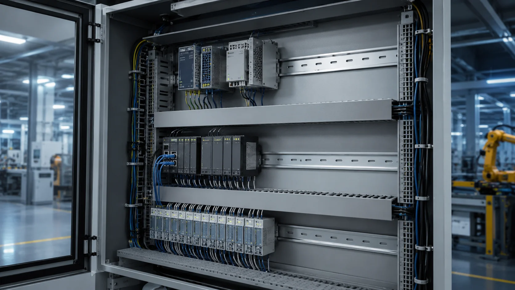
The organization of the DIN rail affects how effective maintenance is performed and the reliability of your system. A lack of proper planning results in a chaotic environment for cabling and a nightmare for troubleshooting. Components should be grouped logically; power supplies should be located on the upper rails, PLCs in the middle and the lower rails for I/O modules. This provides for natural cable flow patterns and reduces EMI (electromagnetic interference). All standard 35mm DIN rails will mount directly to the back panels of electrical control panels. Stepped rail configurations should be used for high density installations; this method separates the different signal levels and improves the management of cables. Do not forget to consider future expansion space as automation systems grow. The minimum planning for future expansion is to always plan on having at least 25 percent of the capacity available on each rail section. When adding to an existing automation system you do not want to have to rewire the entire control panel.
Cable Management Routing Systems
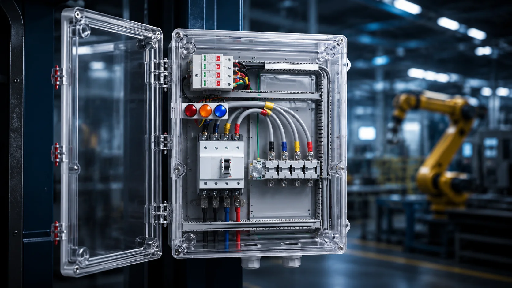
Good cable management gives a professional quality to an installation and creates separation between a good installation and a great installation. Your electric control panel must contain structured pathways for your power and signal cable connections. Use Horizontal cable ducts to provide structured pathway connections between DIN rail levels. This will ensure an organized routing channel and separation of different types of signals. Power cables will be in a dedicated duct separated from communication wiring. Careful planning is required for vertical cable management; for this purpose, install either cable trays or wire ways on the side of panels to keep your cables organized and allow easy access for making modifications. Label every cable; maintaining a system of identification for your cables saves wasted hours during maintenance activities. Use heat-shrink type labels that are suitable for industrial use. Our IP65 rated enclosures will shield your labeling systems from water and dirt.
Electromagnetic Shielding Requirements
Electromagnetic interference (EMI) comes from sources such as motors, control systems and welding equipment within factory environments – therefore it is necessary to protect your control panel box’s sensitive electronics from this interference or damage caused by EMI emissions. When gaskets are installed correctly, they provide electromagnetic compatibility (EMC) shielding when compressed correctly through a consistent closing force on the front door. The latching mechanism we use in our electrical control panel boxes is robust enough to provide constant contact of the gasket and thereby maintains the effectiveness of the gasket as EMC shielding. Cable entries need to be shielded against EMI leakage; shielded cable glands with an omnidirectional shield termination will help maintain the enclosure’s integrity while allowing for the appropriate electrical connections. Before installing any EMI filters, you should take time to consider the effects they will have on cooling; all EMI filters will generate heat and require adequate space for proper cooling. Filters should be located as close to intake fans as possible, because they will cool more efficiently when they receive cool air.
Ventilation Airflow Design
Adequate ventilation increases durability of components and reduces idle time due to problems with overheating. Your electrical control panel box ventilation system must be able to move air efficiently while still providing proper protection ratings for your equipment. Calculate total heat load before selecting the fan for the system. Include all power dissipation from each component including PLC’s, Drives, Power Supplies, Lighting. Remember to add 20% margin in total heat load calculation because it is difficult to predict the ambient temperature changes. The location of the fans within the control panel box affects how the air flows through the control panel. A bottom intake, top exhaust arrangement creates natural thermal circulation, whereas side-mounted fans are usually used for application where space is constrained but must be installed carefully to avoid creating a dead zone at the back of the control panel box. The condition of the filters affects the flow of air through the fan because clogged filters will reduce flow and create greater pressure drops across the filter. Provide access to the filter for routine cleaning/maintenance without removing any critical components of the control panel.
NEMA 12 vs IP65 Protection Selection
Protection ratings determine your electrical control panel box suitability for specific environments. Understanding the differences helps ensure proper selection.
IP65 protection means dust-tight construction and protection against water jets. This suits most factory automation applications where coolant splash and washdown procedures occur.
NEMA 12 provides similar protection but uses different test methods. Both ratings handle typical industrial contaminants like dust, dirt, and non-corrosive liquids.
| Application | Recommended Rating | Key Protection |
|---|---|---|
| Machine control panels | IP65 | Coolant splash, cleaning |
| Factory floor I/O boxes | IP65 | Dust, moisture |
| Control room installations | IP54 | Basic dust protection |
I-closure electrical control panel boxes meet IP65 standards with proper gasket installation and cable gland selection. We provide complete sealing solutions for industrial automation requirements.
System integrators trust IDIS India for reliable automation enclosures. Our engineering team helps select appropriate sizes and configurations for specific applications. Contact us for detailed specifications and application guidance – protection requirements may vary depending on your installation environment.