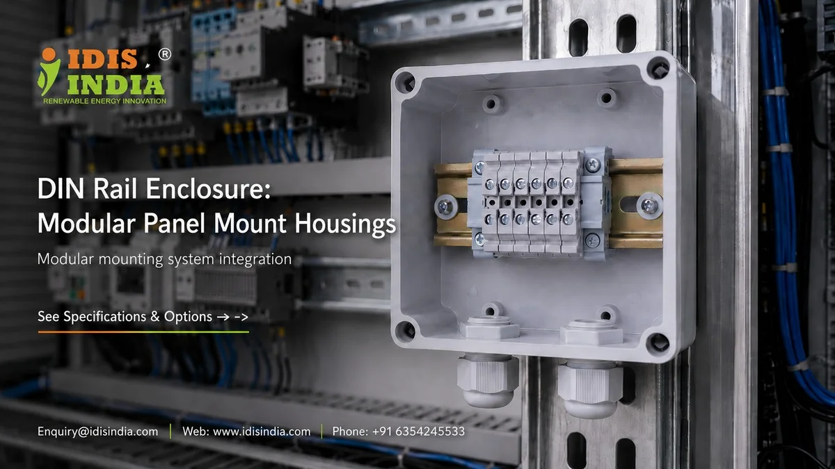
Panel builders constantly encounter difficulties when attempting to combine several different parts into small control systems. DIN rail enclosures provide a solution to this issue by giving the panel builder standardized mounts which will fit correctly on any pre-existing piece of automation equipment. Here at I-closure, we realize that building an accurate panel and designing a quality control cabinet requires extreme precision. However, what makes a DIN rail enclosure successful? It’s not just building mounts; it’s creating reliable, repairable control systems that technicians can feel confident working with.
DIN Rail Clip Mechanisms for Secure Component Mounting
A good repair begins with the clip design. The purpose of the clip is to hold the rail so it can be installed easily and removed readily, without damaging the enclosure. The clip is responsible for maintaining retention to the rail and must have consistent retention force throughout the temperature range. The quality of the clip has a direct impact on how long the panel builder can expect the enclosure to function reliably. The cheapest clip will create a loose connection over time and therefore cause intermittent connections, which will lead to failed systems. The DIN rail clips we design are made from premium-quality materials so that they maintain spring tension after being assembled thousands of times. Additionally, the installation process is critical; our clip design allows for one-handed installation of a cable or to support the next part being assembled while installing the first part. The audible click sound will tell you that the part is seated correctly; no second-guessing.
35mm Rail Standard Compliance Across Industries
Because of its Mechanical Stability, the TS35 Rail has become a Universal Standard in all General Bar Mounting Systems. TS35 Rails are 35mm wide; TS35 Rails are compatible with all other 35mm wide Rails produced by Most Manufacturers. However, the performance of each Specific Manufacturer’s Finished Product (Enclosure) Will Vary Consistently to EN 60715 Specifications for use on 35mm Standard Profile Rails. The Channel Depth (Tube) of the Enclosure will provide for the Whether the Rail Section Width is ANSIA/CUL Approved to EN 60429 T : Well Understood and Accepted. Most rail profiles conform to ANSIA/CUL Approval (Standard Rail Profiles) and are T: (THERMAL EXPANSION). These characteristics of the Channel Provide a Positive Rail Fit Without BINDING. The Standards Regulating RAIL DEPENDENT APPARATUS Are More STRINGENT. The primary code is EN 50155; additional compliance requirements for RAIL DEPENDENT APPARATUS Include Improved Resistance to Vibrations & Improved Temperature Cycling Performance. i-closure Enclosure will Satisfy ALL EN 50155 Compliancy to RAIL DEPENDANT APPARATUS DESIGN STANDARDS for OUTDOOR® Railroad App.
Snap-Mount Retention Force Testing for Vibration Resistance
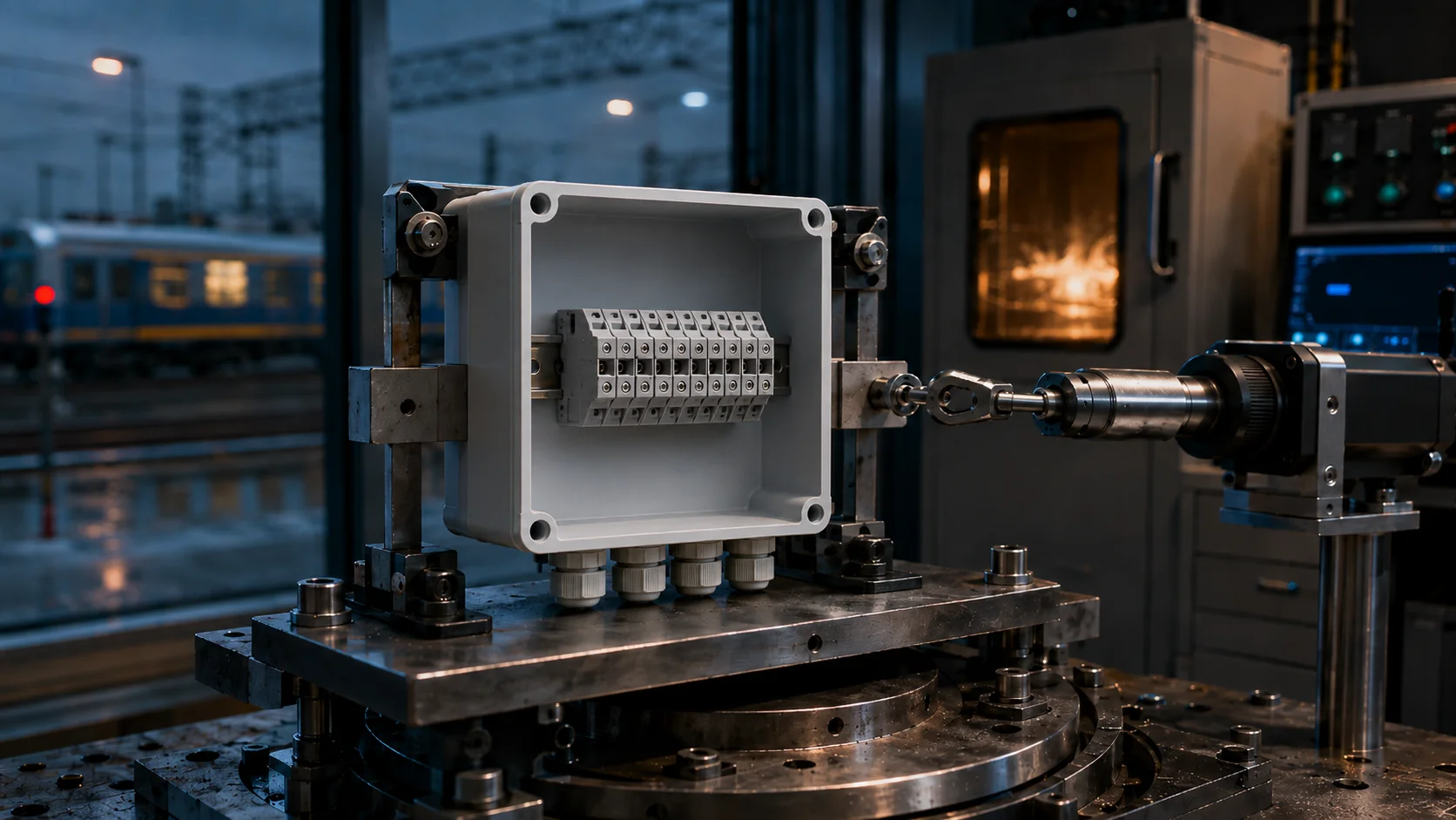
What is the maximum level of loads that your DIN rail mounting system can support until it breaks? This is not just an academic question because in the real world, enclosures will encounter a large amount of mechanical loading due to their application. For example the equipment mounted to platforms will see a lot of mechanical vibration from trains that pass over the platform. In addition to this, point machine controllers need to be securely mounted to withstand ground-induced forces. In order to test retention solutions, we use calibrated force gauges to confirm that retention solutions meet at least the minimum required retention forces. There are four areas that retention clips lose their retention due to: Continuous vibration from 0 to 100Hz Temperature cycling from -25 to +70°C Shock loads equivalent to a 3G acceleration Long term deformation or adjust to the load over time These test conditions are more than checkboxes – they represent real-world situations where the reliability of the equipment will directly affect safety and will affect the continuity of operations.
Modular Expansion Planning Methods
A control system will usually develop over time, starting with a basic PLC coupled with an HMI interface plus comms modules and the addition of more I/O blocks. Smart panel design will allow for future expansion by using modular planning techniques; for example, our DIN rail enclosures stack neatly with no gaps or misalignment, and we have used a design for the mounting feet to allow for an even, uniform distance between enclosures while providing proper airflow and access for maintenance. A systematic approach to planning will also help you when you need to expand your system in the future, i.e., have a good cable management plan. As more modules are added to a panel, you will find yourself with many more wires, and if your panel is cramped, it will create a potential maintenance nightmare! The Housings designed by IDIS India have cable routing channels built into them to provide your future expansion without having to do any retrofitting.
Panel Depth Clearance Calculations
The depth of the panel frequently limits how the control cabinet is designed. There is a significant need for making sure that any off-the-shelf/din rail components fit within your design parameter based on what the manufactured dimensional needs are. In addition, if planning is not performed adequately, there may be issues with clearance conflicts, or cabinets being too large or too small (based upon zones). Standard criteria, which must be calculated into the design of the panel are: (1) The body depth of the components, with their terminal connections; (2) The bend radius for the cables; (3) The clearance requirement for the door, when opened; (4) Service accesses for maintenance; (5) Airflow paths for heat transfer (via convection). We have basically engineered all our enclosure cross-sections for the optimum space utilization (including minimal clearance separation). Our slim-line designs reduce the amount of total panel depth needed (usually resulting in the use of smaller enclosures), without sacrificing structural integrity.
DIN Rail Load Distribution Analysis
Installers frequently overlook weight distribution rules while working with DIN rails. Putting too much weight on a section of a DIN rail will create stress spots that could cause the mounting to fail as well. A proper load analysis considers both static weight as well as dynamic forces acting on the mounted object. Vibration increases the effective weight of an object being supported, especially if the vibrations’ frequency matches the natural frequency of the mounting system. If the mounting system is installed on a railway, it must also consider additional loads caused by the movement of the train causing ground movement under the mounting system. We provide load rating information for our enclosures to assist with the design of your systems. The design of the mounting clips on the din rails spreads the load over the entire length of the din rail, thereby preventing stress points from occurring at the mounting clips. Using this method greatly improves the life and dependability of the complete din rail mounted system.
Automation Component Stacking Systems
To optimize density, today’s control panels use multiple stacked function blocks; however, such a configuration leads to new challenges: heat build-up, increased complexity in routing cables, and difficulty accessing certain components during troubleshooting. In order to overcome these issues, I-closure was designed with various features. For example, the ventilation slots allow convection cooling of all stacked units. Cables enter through aligned points, which simplifies harness routing. Easy access to multimeter probes is provided by an appropriate housing profile; thus, there is no need to remove any other stacked components to gain access. A further benefit of the I-closure solution is the quality of its PC/ABS materials; they have high dimensional stability with thermal cycling and will not bind when stacked. This characteristic is especially important in unattended installations where remote resetting is required.
Railway-Specific Applications and Compliance
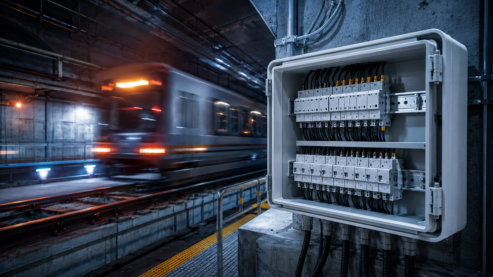
Railway systems have unique requirements that standard industrial enclosures may not provide. Rail tracks are subject to extremely high and low temperatures, constant vibration, and stringent fire regulations. Our railway-approved enclosures have passed all EN 45545-2 fire tests, thereby receiving HL2 and HL3 fire ratings depending on the zone they will be installed in. All materials used are non-combustible with low smoke production, which is especially critical when installing in tunnels or enclosed platforms. RDSO and IRS also add additional fire requirements above and beyond European standards, such as specific colours, labelling modifications, and documentation formats. IDIS India will maintain current certifications to meet railway project requirements. Do you have specific requirements for building panels? Our engineering staff would be happy to provide you with further detail, including specifications and compatibility for your upcoming projects. Please contact IDIS India to learn how our DIN rail enclosures can help you simplify your design of control systems.