Did you come up with a brilliant idea for a product, but now have difficulty with designing the plastic enclosure? Many other product engineers and startup companies reach a roadblock during the transition from an idea to reality. When you place your electronics inside their plastic enclosure, you are not just giving your product a protective outer shell; you are also creating an opportunity for the outside world to visually see your product as well as interact with it through the use of the electronic device. The team at IDIS India knows that enclosure design services involve much more than just constructing a simple box around your product. Rather, their talented enclosure design team engineers provide solutions for the protection, performance, and presentation of your product within an engineered enclosure. With over 1,200 successful enclosure design projects completed, the experienced team members have helped numerous customers develop their first products and build prototypes to enter the marketplace. The right enclosure design partner can have significant impact upon both your project schedule and budget, whether you are developing your first product or expanding an existing product line.
Design Brief Requirements Analysis
To define your enclosure correctly you need to first understand exactly what you really need in terms of what your product will actually require (not what you think). Through our requirements analysis we can identify the specific environmental factors which will determine how your device will be used i.e., is it going to be inside an office building or out in an industrial environment? This will then determine if you simply need a normal level of protection or if you require our range of IP65/IP67 rated Products. Many designers are often shocked at how much room for additional functionality will be required to accommodate their devices’ compact PCB design. Other factors such as thermal management, cable routing, mounting requirements, etc., will affect the overall architecture and design of the enclosure. However, the one thing that is usually missing from a design brief concerning the end users experience is user interaction patterns with the device. How will an end user interact with the device? Is it going to be wall mounted, portable or on a desk? The answer to the questions above will help dictate which materials will be used, the thickness of the enclosure walls, and what type of structural reinforcement will be necessary. Finally, regulatory compliance requirements must also be analyzed from the outset, as they can influence the type of materials and methods of construction to be used, rather than just being an afterthought like CE marking, RoHS compliance, and safety standards.
Critical Design Parameters
Temperature ranges for operation and cooling requirements, Ingress Protection ratings based on the environment, Entry point and sealing requirements for cables, Mounting types and load-bearing capabilities, User interface options and accessibility requirements, Regulatory compliance and ways to obtain certification.
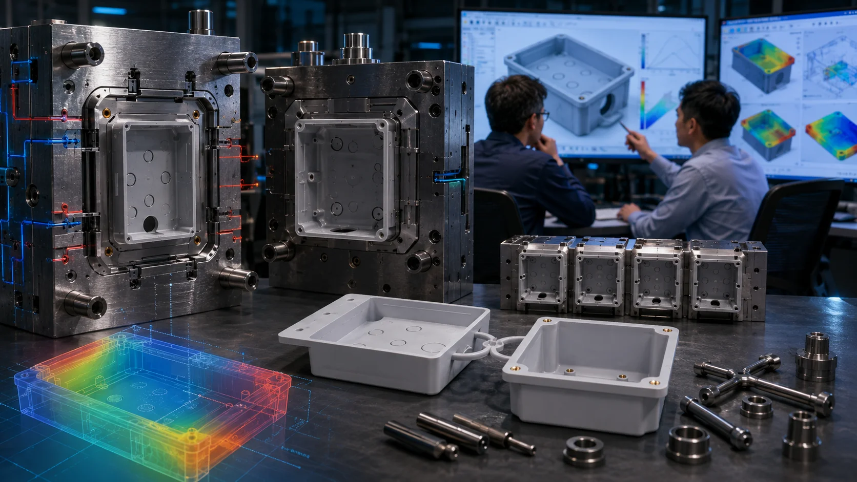
CAD Modeling Workflow Integration
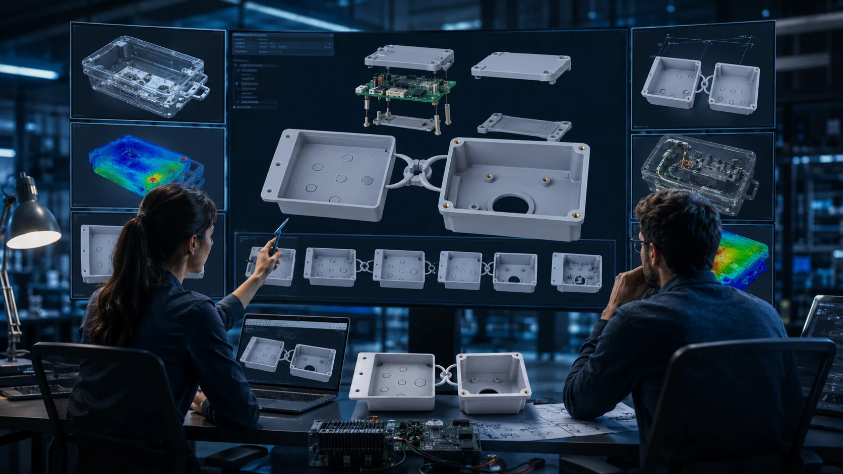
The latest enclosure designs are done in 3D from the beginning. The way we create our CAD models fits into any project development process no matter what design software you use (SolidWorks or AutoCAD, etc.). First we create a model of your PCB layout and component specifications to create a CAD model of all components including all connectors, heat sinks, wire harnesses. This prevents the unpleasant surprises when the prototype components don’t fit together as expected. The engineers at I-closure use parametric modeling methods that allow you to change design elements throughout the design process. For instance, if you need to change the thickness of a wall to save on costs, every time that change is made, the entire CAD model gets updated automatically and still retains all of the clearances that are important to create a structurally sound product. By using simulation methods built into the current CAD workflow, we can predict how a product will perform in a realistic environment. Using simulations for Example; stress analysis, shows the areas of a model that may need additional support. Thermal modeling predicts hot spots that can develop before they occur. Plus, we offer you native CAD files in many of the formats that you would use so your Mechanical Engineering team can place or use your enclosure designs as part of their assembly drawings and documentation.
Collaborative Design Features
Real-time modeling and tracking of revisions; integration of change management to capture the entire approval process; automated solutions to check for interferences and confirm clearances; simulation of material properties to validate strength and integrity of structures; compatible exports with all major product manufacturing systems.
Prototype Iteration Cycles
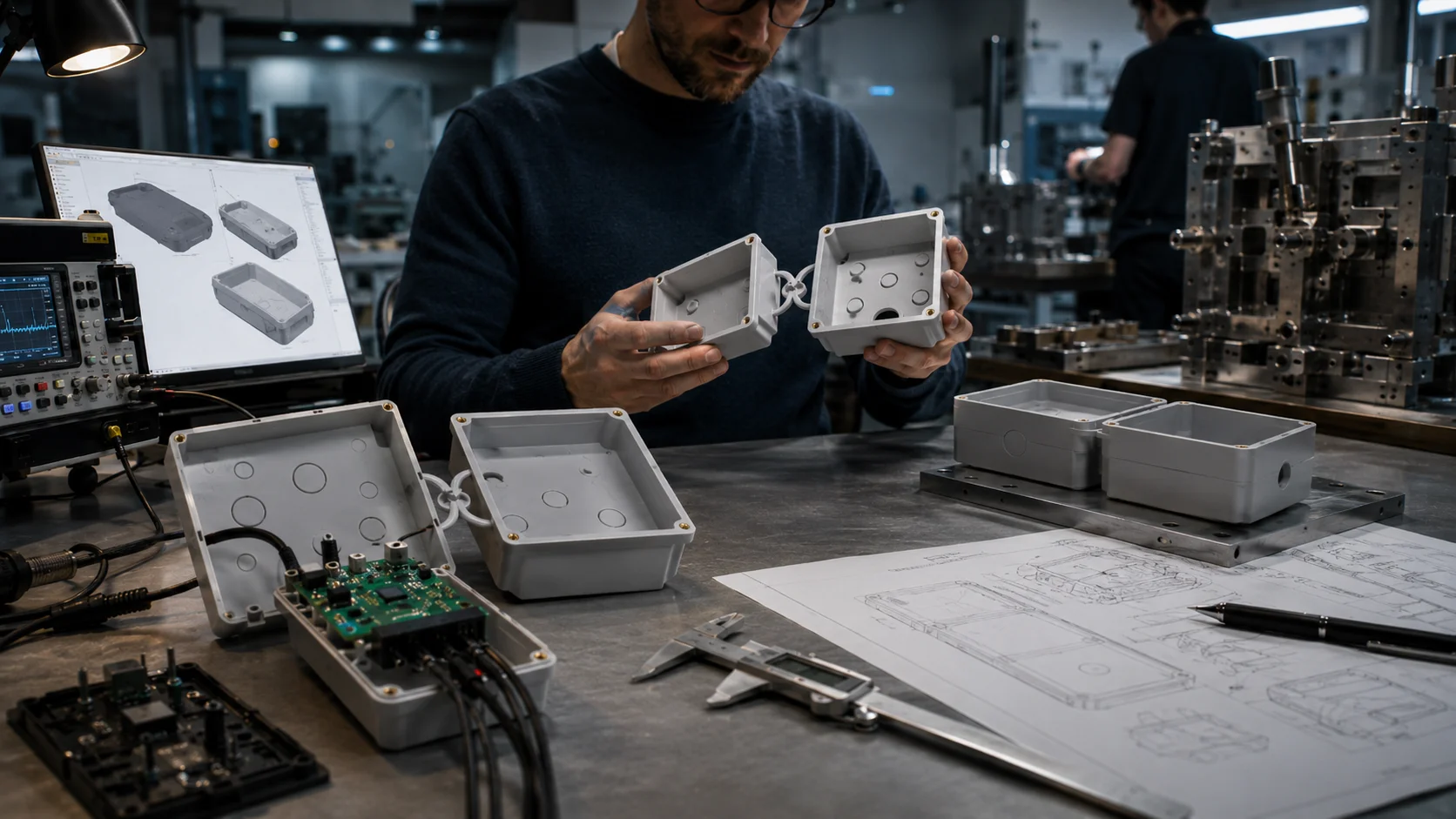
How a concept translates into actual plastic parts differs from what you may see as a graphic representation of the concept displayed on screens. For this reason, we have developed rapid prototype cycles to allow you to explore your concept in terms of touch, testing, and refinement. The first round of prototypes (first iteration) establishes fit and functionality. Is your PCB assembly mounted properly? Do all cable connections work? Are all user interface elements placed appropriately? These prototype forms validate most of the original design assumptions. The second round of prototypes (second iteration) deals more with the aesthetics and ergonomics of your proposed design. How does the prototype feel in the user’s hand? Does it appear professional in its intended market? You may be able to identify ways to simplify your design or to add additional features through this process. The third round of prototypes (final iteration) attempts to establish whether or not the design can be manufactured as intended. Is your prototype able to be efficiently molded? Will the final prototype meet the desired wall thicknesses consistent with manufacturing techniques? The production-intent prototype rounds together the design work with the manufacturing work. Our prototypes are typically on a 2-3 week (or longer based on your prototype’s complexity and material requirements) prototyping cycle. Please note that typically, ABS prototypes will have a shorter time frame than polycarbonate or PC/ABS prototypes due to their material processing characteristics.
Prototype Testing Validation
- Drop testing and impact resistance evaluation
- Environmental exposure simulation
- Ingress protection verification
- Thermal cycling and stress testing
- User interface functionality assessment
DFM Cost Optimization Reviews
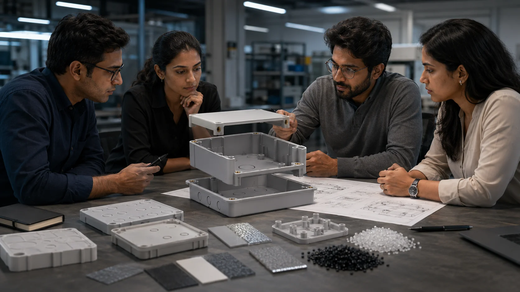
Design for Manufacturing (DFM) refers not only to the ability to create parts that can be molded, but also to make those parts profitable. DFM reviews help identify places where cost can be reduced without changing the way a part works or looks. By optimizing wall thickness it is possible to save money even though, in some cases, this may not result in stronger enclosures due to wall thickness alone. However, by using smart ribbing and properly reinforcing the part, it is possible to achieve the same level of strength and performance while using less material. Additional opportunities for reducing manufacturing complexity and time are found by consolidating features – i.e., whether or not a number of parts could be joined together to create one molded part? Are there ways that separates gaskets could be eliminated as part of the design of the seal? The selection of materials is evaluated by balancing the anticipated performance with the desired cost. Sometimes the choice of a polycarbonate(Auburn plastic) with an ABS(Audi electronics), can be a compromise between the economic benefits of pure ABS(Austin manufacturing) and the performance advantages of polysine. The surface finish options of a part are also evaluated for the purpose of determining their need. For instance, high gloss(Consumer Products) finishes may look great but generally have a higher manufacturing cost and result in easily visible fingerprints. Textured(Descriptive Terminology) surfaces may provide a better user experience while costing less to manufacturing.
Cost Reduction Strategies
Use of a common standard component for assembly to help eliminate extra assembly cost and complexity of production, use of undercuts in the design for easier ejection of the part from the mold, how to design and position the gates to provide the least number of visible gate marks after the part is ejected.
Tooling Feasibility Assessment
Great designs do not always have an economically viable option for manufacturing. Our tooling feasibility assessment identifies issues prior to the transition to production, therefore preventing large unexpected costs from arising. Tooling costs and production timelines are affected by the complexity of the mold. When designing parts that require deep draws, complex undercuts, or intricate internal features, sophisticated tooling solutions will be necessary. Minor changes to the design of a part can drastically reduce the complexity of the tooling. The location of the parting line will affect both the quality of the part produced as well as the efficiency of the manufacturing process used to produce it. Our assessment will identify the best locations for a parting line to minimize any visible marks as well as maximize the efficiency of the production cycle. Also, there are considerations for multi cavity tooling if production increases. Does the design lend itself to assist with the multi cavity tooling? Are there any design modifications you will need to make to ensure consistent reproduction of quality parts across the cavities? Material flow analysis provides you with an understanding of any potential problems with molding such as short shots, sink marks, and/or warpage. These areas can then be improved through design change in the manufacturability and quality of the part.
Tooling Optimization Factors
Evaluating the complexity of the core and cavity design The design of the cooling channels to optimize cycle times. Projecting the injection system to ensure the best quality for the parts . Optimizing the design of the runner system to minimize material waste. Ensuring that appropriate serviceability and tooling lifespan are met.
Production Scale Transition Planning
Designing an enclosures design from concept to real-world use requires lots of planning and testing to make sure everything will work together. With our transition planning, we’ll help you figure out how well your enclosure design will fit with your production strategy (whether you’re doing low-volume production or high-volume production). This will help you decide which type of manufacturing will work best for your projected volume and timeline constraints. It’s important to build quality control systems into your product right from the start; they should not be an afterthought! Design details must be established upfront (what are the critical dimensions for quality control?), how you will consistently perform the proper tests to verify your enclosure meets an Ingress Protection rating, what steps you will take to assure all of your enclosures will look alike over all production runs, and how your supply chain comes into play to provide support for sourcing material and inventory management (lead-time, minimum quantity, supplier qualification, etc.). Transferring the documentation package from design and manufacturing teams should go smoothly, which requires complete and accurate technical drawings, specifications, and quality requirements that make it possible for production to get set up efficiently and produce consistent results.
Production Readiness Checklist
Manufacturing process documentation for final design approval and validation Specification of product quality standards Development of a qualified source for the materials required to produce the product Manufacturing Tool Verification and Production Process Optimization Defined Standards of Quality Inspection Procedures
Engineering Change Control Systems
Products change as they are developed, and this creates challenges from the design engineering perspective in terms of doing the proper engineering change control (ECO) to manage those often-identifiable changes and to keep things from getting out of control and running up costs during the development (aircraft manufacturing or whatever system has to do with building line items), determining the impact of all of these ECOs (change impact analysis) on how these changes will affect existing tooling, inventory on hand, production schedules and the overall production system.
Also, changes that appear simple on the surface sometimes cause a chain reaction of events or problems throughout the entire manufacturing system (i.e. different versions of enclosures for a Printed Circuit Board [PCB]).
The ECO system will maintain these relationships between these design versions of products and prevent these costly mismatches. In addition, through our approval processes, we manage and ensure that all affected parties have reviewed and approved any proposed ECO before it is implemented.
Engineering approvals are required for technical changes; management approval is required for all cost impacts; and customer notification is required for quality issues. Coordination of implementation schedules is also critical when multiple production streams are being impacted by these proposed ECOs, such as how modified enclosures should be introduced into production, how will we manage existing inventory, etc.
Ultimately, the outcome of these logistical challenges will lead to the success of implementing the actual change. In our experience, IDIS India has successfully managed thousands of different engineering changes across our vast customer base through our ECO system. We recognize that change management involves more than just documenting what happened; it is about maintaining the quality of your product and meeting your delivery commitments while you are continuing to modify it.
Change Management Best Practices
An extensive analysis of change impact, as well as a complete cost evaluation, A clear delineation of authority and responsibility for approval, A system of documentation with a complete “revision control” system, The coordinated installation of the affected systems, Validation and evaluation of performance after the project is completed. If you’re ready to turn your enclosure concept into a manufacturing reality, contact the Engineering Design Services Team at I-closure for their expertise and practical manufacturing knowledge- from design to production scale. They will be your partner for creating enclosures that protect, perform, and succeed! Contact IDIS India right now to talk about your specific design requirements, and see how we can help you reduce your time to market while enhancing the quality and cost-effectiveness of your products.