An electrical installation’s circuit breakers need to have a dependable, secure place in which to reside; this may be achieved through the use of MCB distribution boxes, which can also assist you with organizing the distribution of power in one place that is easily accessed by you. Choosing the proper distribution box when you wire a home or put in a commercial panel will make a big impact. As of 2017, IDIS India has provided over 1200 MCB enclosures to customers. The IDIS I-Closure series includes MCB enclosures specifically designed for use with circuit breakers, including boxes for one-phase residential applications to boxes for multi-phase commercial applications.
MCB Way Configuration Planning
Most contractors miscalculate their way requirements. In the case of distribution boxes, the term way represents each individual MCB slot. Most commonly, these boxes come in 4-way, 8-way, 12-way and 18-way options to accommodate MCB’s. What is often overlooked is future expansion. An 8-way distribution box may appear to meet your present needs, but, should the customer eventually require additional outdoor lighting or electric vehicle (EV) charging stations, what solution will you have? Regardless of whether you’re currently using a polycarbonate distribution box, they can easily accommodate any MCB configuration based on requirement and future growth. The modularity of all polycarbonate distribution boxes allows you to begin with limited requirements and then expand as needed. Because these boxes are manufactured via injection molding, each compartment maintains consistent dimensional specifications relative to the MCB’s. When creating your wire configuration, also take into account the distribution of wire loads among the individual MCB circuits. Do not put more than one higher amp circuit on either side of the distribution box; if you do, you will create uneven heating of the box and/or neutral connections. Therefore, in order to achieve the most efficient method of thermal management for your electrical system, spread out the wire loads across all of the way configurations.
DIN Rail Mounting Systems
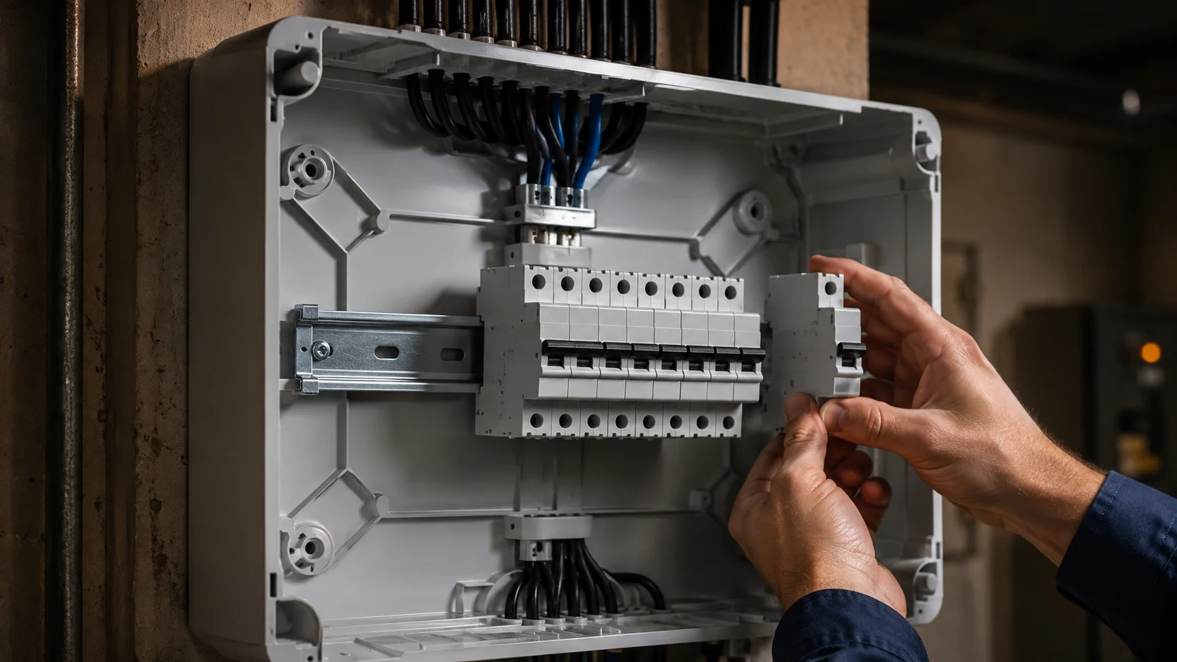
Mounting DIN rail can be deceptively easy to install and provide great results, however, once you do install them, if you have any type of wobbling in your installation it may be difficult for you. This is not due solely to the quality of the DIN rail alone, but also has to do with how the mounting of the enclosure is supporting the rail. Our ABS Distribution Boxes come standard with a built-in clip system that keeps the DIN rail from shifting while you are installing your MCBs. No longer will you have the frustration of having your DIN rail shift just at the time you are snapping on your last breaker. The mounting points are designed to evenly distribute any stress that is applied to the enclosure back panel. Standard 35 mm DIN rail will fit perfectly with our distribution boxes; however, please check your MCB specifications; there are some manufacturers that use slightly different clip designs for their MCBs. Generally speaking, however, our box should support most popular brands of MCB without modification. As a tip for installation, when you attach the enclosure to the wall, ensure that you mount your DIN rails first. This application method will give you better access to your mounting rails and help prevent back problems. The DIN rail will “snap” into place tightly when you wiggle the rail and will not have an audible sound of play at that time.
Busbar Connection Methods
The way that busbar connections are designed is essential for the success of your installation; if they are not designed properly, they will create tight spaces, make troubleshooting difficult, and present dangers to personnel. The buses are typically wired in a common sequence; when the main supply comes into the busbar, it feeds to the busbar, then feeds out individual MCB’s from the busbar. Our I-closures are designed to position the busbars to minimize cable crossing and to maximize usable working space. Copper busbars can carry higher currents than aluminium busbars; however, the copper is much heavier than aluminium; therefore, for residential installations with current draw of 63A or lower, the use of aluminium is acceptable. For commercial installations requiring 100A or more, copper would typically be required for all connections.
However, the most important aspect is accessibility. Is there enough room for you to access the terminal to insert your screwdriver? Can you actually see what you’re doing? All the connection points will have a clear sight line when using one of our enclosures.
Phase Identification
Busbars are color coded in order to show which circuits are connected to each phase so wiring mistakes are prevented. The phases are coded as follows : Red = phase L1, Yellow = phase L2, Blue = phase L3. Black or blue for the neutral, and Green/Yellow for the earth. This is a very simple system and is also generally ignored By many people. By clearly marking your phases on the enclosure label, future maintenance will be significantly easier when the next electrician is able to quickly identify the circuits.
Arc Fault Containment Design
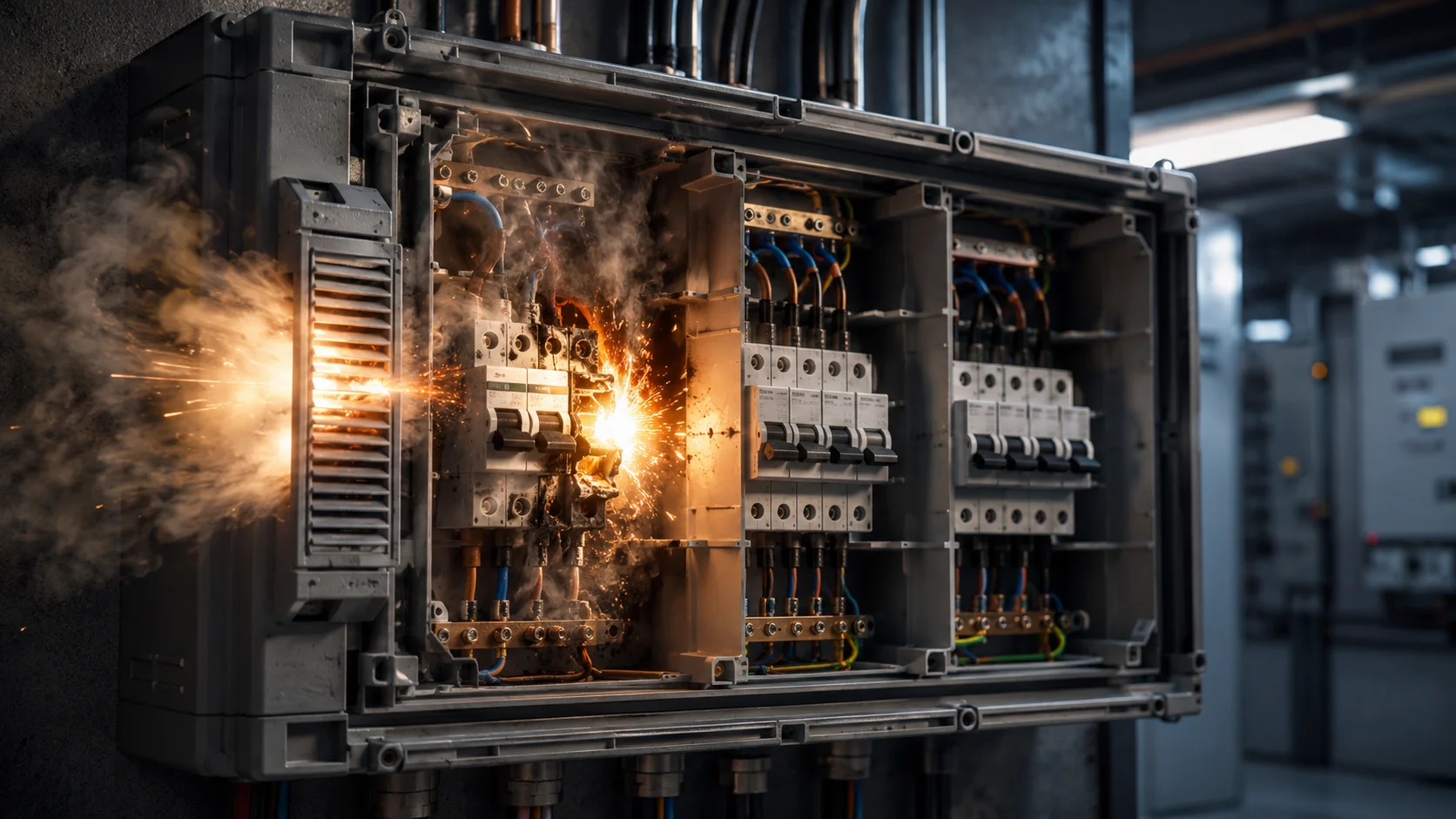
When an arc event takes place, there is an enormous amount of energy generated. The purpose of the enclosure is to keep this energy contained while the cause of the arcing (i.e. MCBs) is fixed. This is not to prevent arcing, as that is the job of the MCBs, but to contain what happens when a MCB fails to contain an arc event. ‘Polycarbonate’ enclosures have much higher resistance to arcs than generic thermoplastics. In addition, polycarbonate will not melt and supports combustion and, therefore, meets fire safety requirements. Ventilation is critical when there are gases produced from an arc event and you need to have a place to disperse the gases. However, you cannot jeopardise the IP protection of your enclosure, therefore, we have built into our designs pressure relief features to ensure the enclosures maintain the IP65 rating in normal conditions and enable the gas to escape if there is a pressure build-up. Internal compartmentalisation of the enclosure also aids in containing the potential energised area by isolating damaged MCB(s) from the other MCBs, thereby preventing cascading failures. This is particularly critical in commercial installations where interdependence of circuits creates vulnerabilities in the system.
Phase Distribution Layouts
Although residential single-phase installations may appear simple, there are significant differences when planning for three-phase commercial installations. Care must be taken to balance loads to ensure the highest level of efficiency and maximize the life of equipment in those types of installations. Three-phase systems should use the same type of MCBs side-by-side by phase, such that circuits on L1 (the left), L2 (in the middle) and L3 (to the right) are visually organized – which reduces errors when wiring and speeds up troubleshooting same type of circuits. An additional consideration that needs to be thought about in your installations is not only how the circuit is wired together electrically, but also how the circuits can be practically installed. For example, a heavy-duty circuit connected to a motor starter will need much more clearance than a standard lighting circuit. Thus, it is important to ensure that these types of circuits are positioned where they will have enough clearance for both cable entry as well as connections to ensure ease of installation. Both single-phase and three-phase installations can be accommodated at our distribution boxes – all of which are designed to maintain a logical or visual separation between phases while providing for compact overall dimension within the structure.
Load Balancing Considerations
Neutral currents and system inefficacy will be caused by unbalanced loads. Distributing loads evenly between phases with a proper MCB layout will improve the neutral conductor’s heating, while enhancing the performance of the entire electrical installation.
Neutral Bar Positioning
The safety of the installation and convenience for installation will depend upon the neutral bar’s location. Too close to a hot wire creates hazards, while too far away requires longer runs for connection. Generally, it has been standard practice to locate the neutral bar directly across from (or opposite) the phase busbars; this provides proper spacing along with appropriate lengths of cable between connection points. All enclosures manufactured by us are designed in accordance with this layout and have sufficient creepage distances to ensure safety. You should size your neutral bars based upon the amount of unbalanced current plus any harmonic current that may be produced due to your non-linear loads as LED lighting, electronic equipment, etc., will produce large amounts of neutral current in most cases. Separate earth bars and neutral bars should also be separated because they connect at the main panel and separating earth bars and neutral bars will assist with fault location and meet regulatory requirements in many areas.
Cable Entry Gland Sizing
IP protection issues and safety problems can arise with wrong sized glands. Smaller ones can damage cable insulation, and larger glands can cause insufficient sealing. The most popular sizes within the industry for both residential and light commercial applications are accommodated for by our standard pre-punched IP65 distribution boxes. However, custom sizes can be made for larger projects. When selecting a gland, you need to carefully consider the type of cable going in. Armoured cables will require different glands compared to standard PVC type cables, and multi-core cables will require larger glands compared to equivalent sized single core cables. It’s essential that you come up with a strategy about what type of entry method you wish to use before selecting the enclosure itself. The position of the gland entry point also influences how you will wire the inside of the enclosure. For example, using bottom entry could protect against unwanted weather however could also be more difficult to install. Utilizing side entry will allow for easier access but will need to be sufficiently sealed against moisture and rain. Generally, you should avoid using a top entry for any type of outdoor installation.
Environmental Sealing
The IP65 rating signifies that the device is secure against dust particles and jets of water. Generally suitable for most distribution box applications. Testing has confirmed that the seals perform as intended in real-world conditions and not just laboratory tests. Please note that the IP rating relates to the overall assembly – enclosure, gland, and door seal; therefore, any installation error in a gland can invalidate the entire system.
Application-Specific Solutions
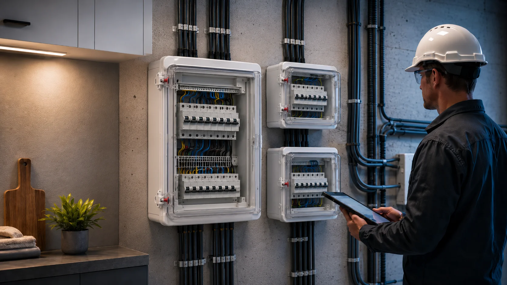
Based on your installation’s requirements, various types of applications require different solutions. Residential electrical distribution boxes tend to be geared toward space utilization and accessibility. Commercial electrical panels typically will have higher amperage capacity and improved wire/cable management systems. If your application is for sub-distribution, you will want to make sure that you have coordinated upstream protective device tripping (MCB rating coordinated with main panel protective device rating) to prevent nuisance outages and facilitate fault location. IDIS India manufactures a complete line of distribution boxes to meet the needs of all these types of applications. Furthermore, our professional team can help provide you with any specific needs or I-closure model recommendations necessary for your project. If you are in need of professional recommendations on MCB distribution box selections, please contact our technical support staff for assistance on your application-based recommendation and up-to-date product availability.